The MGA With An Attitude
GENERATOR TO ALTERNATOR CONVERSION - AC-101
RELAX..... Some people make this job look difficult when it is really simple. That's because they get busy telling you how to modify things their way, and usually forget to tell you how it actually works. When you know how it works, you have more freedom to do it your way.

First consider the diagram above showing the original MGA charging circuit with generator and control box hooked up to positive ground and twin 6V batteries.
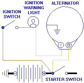
 Then check out the simple circuit on the right. This is all that is required to make a modern internally regulated alternator work. Connect the alternator power output terminal to the battery, and connect the signal terminal to the ignition warning light. Then check out the simple circuit on the right. This is all that is required to make a modern internally regulated alternator work. Connect the alternator power output terminal to the battery, and connect the signal terminal to the ignition warning light.
To satisfy the alternator's requirement for negative ground, the vehicle electrical system needs to be converted from positive to negative ground, also a simple task. The rest of the conversion is just switching a few wires to bypass the original control box, which is no longer needed.
[page break]
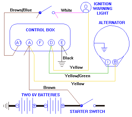
Below is a diagram showing results of the most common conversion instructions. Convert vehicle system polarity to negative earth. Physically mount the alternator, and connect the same two wires which originally serviced the generator. Then at the control box, move the fat charging wire from the "D" terminal to the "A" terminal, and move the small signal wire from the "F" terminal to the "D" terminal. That's it. Test the system to be sure it is charging, and drive it away.

This does effectively disable and bypass the control box function. Most instructions will mention that it is convenient to use the original control box as a terminal block for connecting the wires. But they never seem to get around to telling you how to remove the control box, which always looks silly to me when we know the new alternator doesn't need it. But of course removal is also simple.

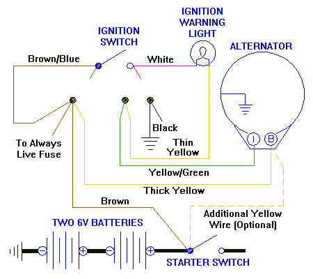
All you need do to disconnect the original control box is to move the single wire from the "A1" terminal to the "A" position, then disconnect everything and splice the wire ends together as shown here. Then you can remove the original control box, put it on the coffee table for a conversation piece, or sell it to someone who may need it. If you also do a proper job of splicing the wires here, like solder the ends and heat shrink cover the joints, then you can press it all together and cover it to make it look like part of the trunk of the wiring harness.
The reason you see two black ground wires connected here is because this is where the screen wiper motor is grounded in the MGA. This entire wire bundle is on the end of an independent branch of the wiring harness. So once you have it properly sealed up you can tuck it behind the heater box, out of site, out of mind. And you can take a copy of this last diagram and slip it into your workshop manual. Or you might want to attach it to a copy my page with the original generator charging circuit. The important thing is keep a record of this modification with the car for all eternity for maintenance purposes (and so you do not become the DPO).
Oh you did notice that extra "optional" wire in the last diagram? Bear in mind that your new alternator may be capable of putting out about double the current of the original 22 amp generator. Attempting to pump 40 amps or more through the original 12 AWG charging wire is not such a good thing. If you are charging a dead battery or jump starting another car with a low battery, this undersize power wire could overheat, or it could reduce the output of the alternator. A good solution here is to install an additional 12 AWG power wire in parallel with the first one to double the current carrying capacity. If you were to terminate this new wire at the same splice where the original wire goes, the increased current could still overload the brown wire between that junction and the battery cable when charging at full output. It is better to connect this new wire directly to the battery cable, and leave the original brown wire to supply the normal amount of power to the rest of the electrical system.
As an alternative to this double wire scheme, you could run one larger wire, at least 10 AWG, from the alternator to the battery cable. Then the original charging wire would not be needed, and can be disconnected and properly terminated (hidden), leaving only the one new power wire on the alternator. Perhaps you might deem it prudent to install an even higher output alternator, as for a high output audio system or high power rally lights. In that case you need to increase the size of the charging wire accordingly, like 12 AWG plus 10 AWG, or a single 8AWG for up to 60 amps, .... etcetera?
When mounting your new alternator, be sure attach it securely to the engine. If the tail end of the alternator is weakly mounted and left to vibrate it might eventually fatigue and break one of the mounting ears on the alternator, and a broken ear on the case may not be a valid warranty exchange. Even worse, some replacement water pumps now have an aluminum casting, and the generator mounting ear on the water pump is notoriously weak and prone to break with the slightest disturbance.
A long threaded rod with jam nuts to join the original generator bracket to the back of the alternator is not much better than nothing. Running a longer threaded rod the whole length front to back with half a dozen jam nuts is only a little better. Placing spacer tube(s) on the threaded rod so it can be pulled up tight with a single nut on each end gives a big improvement in rigidity. The best method, if you don't mind the price of the part, would be to forget the long bolt or rod, and install the extended rear mounting bracket from the late production 1275 Spridget. See Moss Motors part number 130-115
Now that you have a handle on the simplicity of the wiring, I can refer you to a few other web sites with various alternator models and pictures.
Here is a link for MGA or early MGB conversion from Jim Morton with Lucas 16ACR 34-amp or Lucas 18ACR 43-amp alternator.
http://www.britishmotoring.net/bm0304/alternator/alternator.html -- (Note: the original web page no longer exists, so the link now goes to an archive file in The WayBack Machine).
Pictures are not so clear, but this one has a long through bolt and double tube spacers for the pivot mount. It also gives dimensions and a part number for the new shorter fan belt required with the small pulley on the alternator.
There is mention of installing a 35 amp circuit breaker in line with the charging wire at the back of the alternator. I'm not sure what that would accomplish. If there was a short to chassis ground in that wire it would be a hot short across the battery, and a circuit breaker at the alternator would not be in the circuit. The only thing a circuit breaker in that position would protect for would be a short to ground inside the alternator. If you wanted to use a circuit breaker to protect that wire, it would make more sense to put the breaker at the other end of the charging wire, between the charging wire and the battery cable connection. I'm also not clear on how it should "theft-proof" the car. Disconnecting the circuit breaker would only stop the alternator from charging, but the engine would still run.
This web page also gives instructions to effectively gut the original control box, toss out the relays, and rewire some things internally. That just seems like a waste of a good control box to me. It also makes a non-standard part that can never be replaced off the shelf. Perhaps the intention is to keep the original wire connection sequence on the control box for original appearance. But it's not going to be concours with an alternator anyway, so I don't see the point.
Finally one of my favorite links (maybe I should have put this one first). It is a PDF file document from Moss Motors giving installation instructions for their MGA alternator conversion kit.
https://mossmotors.com/media/instructions/130-078.pdf
This is very thorough indeed. One of the first notes is for the MGA 1500 model to relocate the ignition coil from the top of the generator to the inner fender. I have long since done this for my MGA 1500, just as a matter of all around service convenience. If you back up to Jim Morton's web page you can see a picture of the 1600 type coil bracket on the engine mount. That seems to fit, barely, but I would still prefer to put it on the inner fender.
The Moss instructions also cover swapping electrical system polarity from positive to negative earth, covering an odd ammeter installation and electric fuel pump conversion (when necessary). It also covers some unique issues with installing an alternator with the Moss supercharge kit. There is a picture of the extended rear bracket (which I highly recommend), so you wouldn't need to fiddle with the threaded rod and tube spacers. There is also a picture of a "yellow wire tap" device for connecting two wires together in lieu of a piggy back Lucar connector.
That should keep you busy for a while. As always, all comments welcome. If anyone has used a different alternator I would like to hear about it. If I should ever get the urge to install an alternator on my MGA, I might post a few pictures of my own.
Addendum August, 2009:
This problem that is addressed in another article on the Moss Motors alternator conversion, but the question keeps surfacing anyway, so I will reproduce the question and answer here.
At 08:36 AM 8/3/2009 -0600, Ken Larkins in Sussex, England, wrote:
"I changed to an alternator and negative earth as your AC-101 page utilizing the existing control box. It works well except that when I turn the ignition off after running the car the ignition light remains alight. If I turn the starter momentarily or disconnect the battery it goes out. Any idea what this is all about"?
Yup. Sometimes when using the original control box as a terminal block for the new alternator wiring, the ignition light will remain on after shut down. Disconnecting the battery momentarily will extinguish it. Sometimes just giving a momentary blip on the starter will drop voltage enough to extinguish the light. This is some problem inside the old control box that keeps the cut-out relay contact connected. The best solution is to disconnect all wires from the old control box as shown in the last diagram above.
Addendum October, 2011:
Okay, I concede. For those who insist on retaining the original control box for appearance only after installing an alternator, you can cure the ignition light problem by inserting an insulating shim between the contacts of the cut-out relay.
|

 Then check out the simple circuit on the right. This is all that is required to make a modern internally regulated alternator work. Connect the alternator power output terminal to the battery, and connect the signal terminal to the ignition warning light.
