The MGA With An Attitude
SIMPLIFIED WIRING DIAGRAMS - ET-101H
NON-FUSED - WITHOUT SWITCH ON
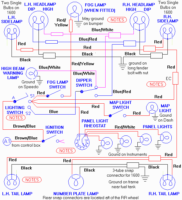
Shown below is the MGA direct circuitry. These circuits are not fused, presumably because a burned fuse would cause all of the lights to go out. The snap connectors labeled EC are located in the right rear corner of the engine bay. For the MGA 1600 the side lamps are single filament bulbs.
 NOTICE: The lighting switch is directly adjacent to the fog lamp switch on the dash panel. The small red wire connecting lighting switch S1 terminal to the fog lamp switch may have both ends extending from the same location on the wiring harness, along with three other red wires which connect to the lighting switch. Any time the harness has been completely disconnected from the dash, you may need to use a continuity tester to determine which two of these five red wires are common. One of those common red wire ends then needs to be connected to the fog lamp switch.
Addendum February 2010:
First note is, there was not originally any "fat" red wire in the harness. Mine has all thin red wires. In recent reproduction harnesses the short red wire that runs from lighting switch S1 to the fog switch was changed to thicker gauge to help identify it separately from the others. This wire being "fat" is visually identified. However, installing four red wires into one terminal on the lighting switch then becomes nearly impossible. Solution here is to install one of the small wires onto the fog switch along with the "fat" wire (all being common on the same circuit). This leaves the lighting switch S1 terminal with one fat wire and two thin wires, and the fog switch input terminal with one fat wire and one thin wire.
Addendum April 2011:
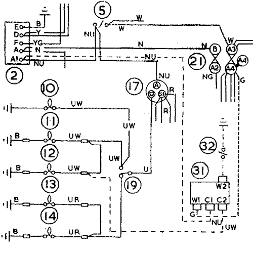
Below is a composite of the Flash To Pass circuit diagram as shown in the 1600 and Twin Cam workshop manuals. It is explained in detail with another article AT-113 in the Accessories section.

|
 NOTICE: The lighting switch is directly adjacent to the fog lamp switch on the dash panel. The small red wire connecting lighting switch S1 terminal to the fog lamp switch may have both ends extending from the same location on the wiring harness, along with three other red wires which connect to the lighting switch. Any time the harness has been completely disconnected from the dash, you may need to use a continuity tester to determine which two of these five red wires are common. One of those common red wire ends then needs to be connected to the fog lamp switch.