The MGA With An Attitude
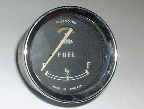
Notice here that the rest pegs for the indicator needle are positioned beyond the ends of the painted scale on the gauge face. These pegs are not a functional part of the gauge, other than to prevent over travel of the needle with sudden motions, which could cause damage to the internal parts. When properly adjusted the needle should travel the length of the curved scale, stopping on the left white line when the tank is empty, and on the right white line when the tank is full. When you turn off the ignition the needle will go to rest against the peg on the left by gravity (no spring in this gauge). If you should have a disconnected tank signal wire or no ground at the fuel tank, then the needle would go to rest against the peg on the right (when the power is on).
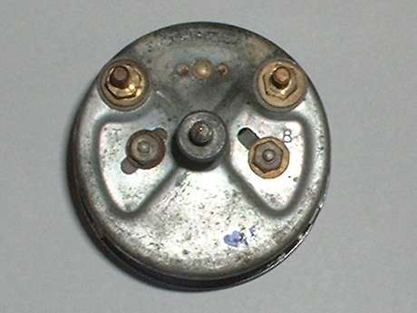
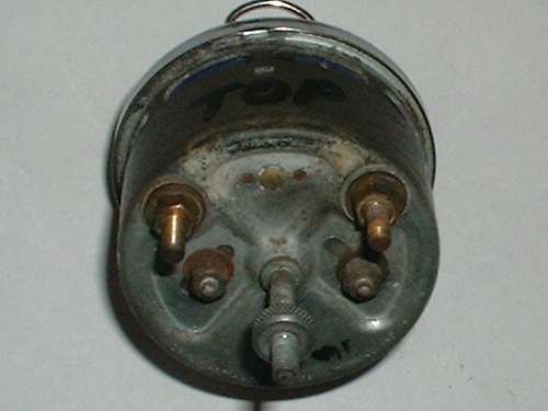
At the back of the fuel gauge near the top there are two electrical connection posts that are insulated from the case. The letters stamped on the case below these posts are "T" for Tank (the wire going to the tank sending unit), and "B" for Battery (the power supply wire bringing 12 volts from the ignition switch). The center stud which is welded to the case not only provides a solid point for mounting the gauge in the dash, but also serves as an earthing connection point. This gauge must be grounded, so there are three wires necessary to make it work.
That small wire loop visible just above the gauge is part of a large paper clamp being used to help position the gauge for photographing. You will see more of it in some of the coming photos. |


