The MGA With An Attitude
INSTALLING MGA CENTER TUNNEL - FR-109
This article resides in the Frame Tech section because the tunnel sections (and floor) are easiest to install to the bare frame while the body is off during a full restoration. If you haven't removed the body but are doing only tunnel and floor, you can still figure it out from here just as well. A prior consideration would be to have any necessary frame repairs finished before starting assembly. Such information about frame welding repairs, mounting rail configuration, captive fasteners and painting are not all on site (yet) at time of posting of this article. Suffice it to say that the frame should be in sound condition and painted as well as desired, and all female threads run through with a tap before tunnel and floor assembly proceeds. It is likely that front and rear suspension may already be installed as well as the gearbox, propshaft, and possibly the engine. The rear flange of the tunnel lies in front of the rear vertical floorboard, so the rear floorboard should be installed before the tunnel.

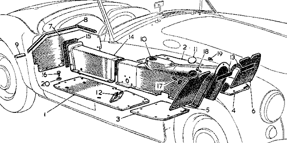
 Above, MGA 1500 with low starter position, through (December 1958). Above, MGA 1500 with low starter position, through (December 1958).
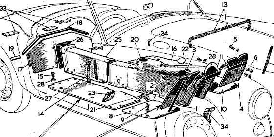
 Below, late 1500 (January 1959 on), all 1600, and All Twin Cam (and "Deluxe"). Below, late 1500 (January 1959 on), all 1600, and All Twin Cam (and "Deluxe").
 Item 13 below is the seal for the horizontal panel on front side of the frame goalpost. Item 13 below is the seal for the horizontal panel on front side of the frame goalpost.

A quick note about a difference between 1500 and 1600 model cars. In very later 1500 production, in January 1959, the gearbox and engine rear plate were changed locating the starter motor a little higher. This required the addition of a large bulge in the upper right side of the tunnel at the front to clear the inertia drive parts on the starter motor. The early model gearbox may be installed in later model cars, but not the other way around. To install a later model gearbox in the earlier production car you need to switch to the later type tunnel with the added bulge on the top right. This also requires a mating trim-back of the toe board to match. Item 34 in the lower illustration is a rubber cover that goes on the bump in the later model tunnel, in the cockpit where the right side passenger may rest their left foot.
One important item to be installed before the tunnel is the frame front bulkhead steel panel. This covers the vertical space on the front face of the frame goalpost just below the crossbar. It also provides the mounting point for a few bolts at the top flange on the front tunnel section, and the top mounting flange for the toe boards. This panel mounts on a flat surface on the front face of the frame goalpost. The original top edge seal was felt. For reasons of both personal health and comfort of the passengers, I suggest it is a good idea to seal the joint here with a little modern silicone latex caulk. Black caulking would be nice with the black painted frame and panel, and wipe off any visible excess caulk which may squeeze out of the joint with final tightening of the mounting bolts.
The tunnel has a larger spot welded assembly for the front 2/3 of the length, having a wide flange around the front and along the sides at the bottom. There is a short space along each side where it is cut out a bit to clear over the rectangular frame cross member. Here there should be (was originally) a rubber buffer (seal piece) on each side so seal where the tunnel "hops over" the cross frame. These rubber bits should be available as reproduction parts today, and they should be quite handy to close up what might otherwise be a couple of sizable draft gaps in the floor. In the absence of these rubber buffers, a large glob of caulking might close the gap in a pinch. The top edge of the tunnel front flange will mate with the frame bulkhead panel, as well as the top edge of the front vertical toe boards. There was originally a felt packing strip running all across from one side to the other to seal against the back of the bulkhead panel. This felt piece may not be available today as a commercial part, but perhaps just as well, as the felt may trap moisture and promote rust. A bit of caulking will seal this joint just as well (and maybe better).
As you are dropping the main tunnel piece into position you may want to check the fit of the hand brake lever assembly. You should be able to install this part after the tunnel is in place, but before the floorboards are installed. In the end the adjoining floorboard, needs a little notch to go closely around the brake lever mounting plate and bolts, and said plate and bolts may be difficult to remove after installation of the floor boards, as two of the bracket bolts are very low in plane with the plywood floor. There is also a hand size lateral brace plate (two pieces) that screws into place inside the tunnel in the area of the hand brake lever near the back of the main tunnel section. While most of the tunnel bottom bolt holes will align with frame holes for mounting the floorboards, one or two of the forward holes in the tunnel bottom flange may carry a weld nut underneath to accept a floorboard screw. You may install a few of the screws for temporary alignment.
Right here, before bolting down the main tunnel section or forgetting what is underneath, lift it up a bit and check the orientation of the long bolt through the gearbox rear mount. That bolt should have the head on the left side and the nut on the right for ease of any future servicing. Direction is with passengers facing forward, so left side is the driver side for us yanks with LHD. If that bolt is installed with the head on the right it cannot be removed after installation of the tunnel. Then next time you need to R&R the gearbox you might suddenly be thinking about how to R&R the tunnel again, seats, floorboards, carpeting and all. Otherwise it might be Sawzall time and in the market for a new bolt. Better to take a few minutes to turn that big bolt around now if necessary. If you're not sure about right and left, the bolt goes in from the side with the larger space, and the nut goes on the side with the smaller space. It does not help that the factory workshop manual and the parts list and most of the aftermarket parts catalogs show that bolt the wrong way around.
The rear 1/3 of the tunnel length (the part mostly between the seats) is another (smaller) spot welded assembly with a flange around the back to mate with the rear bulkhead board, and along the bottom on the sides also mating to the frame. At the front of the rear tunnel part there is a slightly raised but parallel flange all around where it sits atop the front tunnel section. The overlapping flange and gap here was originally sealed with another thin strip of felt. This seal piece may not be available today, could be cut by hand from flat stock, but ditto the comment about moisture trap and rust, and you might just as well caulk this joint too This one is important to seal well, as it ultimately prevents infiltration of oil stains into the carpet with the ultimate and inevitable leakage of a little oil from the engine. Yes, yes, stop laughing. These are after all 1950's vintage cars built with 1920's technology. No other tunnel flanges need to be sealed against the frame, as the rest of the sealing can happen with the floorboards. Align the entire tunnel assembly and secure temporarily with a few screws.
There is also a formed sheet metal tunnel top cover in the area of the gearbox manual shift lever. On very early production cars (perhaps the first 500 cars) this was an integral part of the main tunnel section. This was apparently the cause of the shop manual instructions to remove the seats, carpet, floor and tunnel in process of removing the engine and gearbox. This little problem was addressed very early in production, likely on demand of field service feedback. The change to a removable screwed in place top cover on the tunnel allows for removal of the gearbox remote shifter assembly so the gearbox may be pulled out the front without needing to disassemble the floor and tunnel. The only requirement here is that the center carpet section should be left separate from the rest and should not be glued in place (so the carpet piece mighty be lifted off to R&R the tunnel top cover). It is also a very good idea to seal this joint during final assembly. By personal experience I can tell you that oil stains may encroach through the smallest gap here. Fortunately a rubber gasket is now available for this joint for a modest cost, and it may be reusable through many assembly cycles if necessary. If you happen to have one of the very early production cars with non-removable tunnel cover, future life can be easier if you replace the forward tunnel section with a later style assembly with separate cover. The gearbox should be in place with the remote shift assembly installed before installing the tunnel top cover.
There is a small trick here to make the cover installation easier. The cover is contoured around the sides of the tunnel, making the screw holes a little finicky for alignment. Underneath the tunnel the female threaded fasteners are floating square cage nuts. A few of these may go together with deceptive ease, while the last few may be exceedingly resistant to starting the screw threads. First be sure that all of the floating captive nuts do indeed float. Then test run the screws into each position to be sure the threads run easily with your fingers only. Once the cover is in place it gets tougher to poke through the holes to align the float nuts in the right position. It will help immensely to grind a point on the screw tips like small body screws which will help to spear the float nuts and pull them into alignment. Again be sure the threads run freely after grinding the screw tips. Clean the screw threads with a threading die and clean the float nuts with a tap if necessary. These are #10-32 UNF or SAE fine threads. If you can get this right on first assembly, it may well come back to put a smile on your face again and again with more service cycles in future years.
|

