The MGA With An Attitude
MGA Guru Is GOING MOBILE - (July 1 - July 15, 2026)
Wednesday, July 1, 2026:
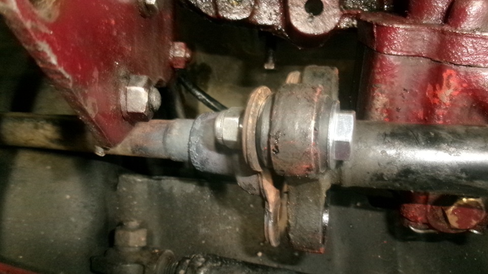
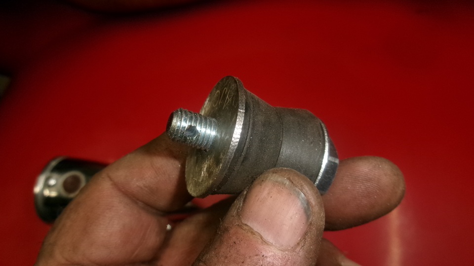
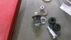
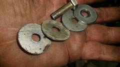
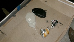
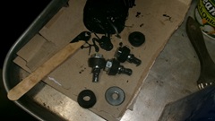
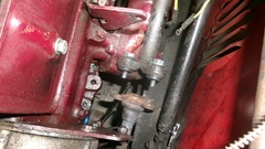
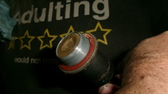
Not enough sleep, but I could get up early to hash out a quick message to the guy with the good idea about the mechanical brake light switch. That "quick" messge took five hours, finishing like a clock strike at 1;30-pm just as the parts order was delivered. Peachy, three brake hoses and a connector kit for the MG TF steering shaft coupling. Hop to it. First picture is the coupling kit parts, shoulder bolt, large washer under the head, two tapered rubber grommets face to face, and a lock nut. Show these assembled and holding the two coupling flanges together. Since the lower part of the coupling had stripped threads where the shoulder bolts should screw in to seat, I figured to build new seating surfaces.


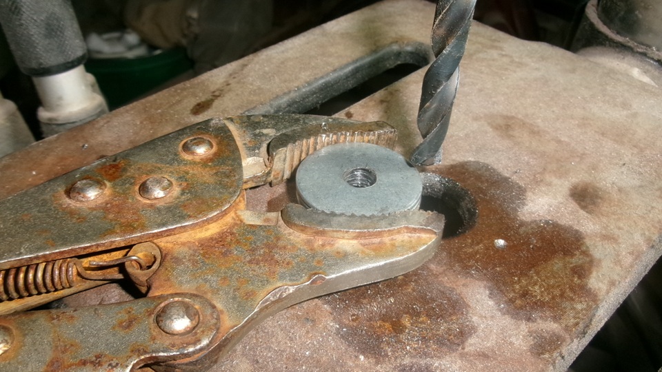
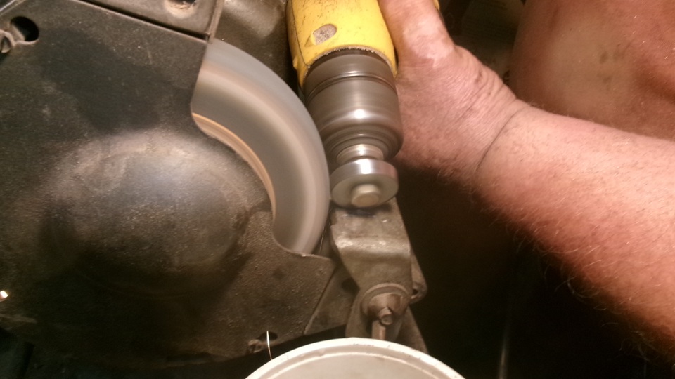
This would start with a few 1/4-inch fender washers, stacked up and drilled to exactly 5/16-inch bore through. Bolt these together on an arbor to hold in the electric drill, and grind down the OD of the stack to 1-1/8-inch diameter. Rub the new washers on 180-grit sanding belt to remove all burrs, and they were good to go.


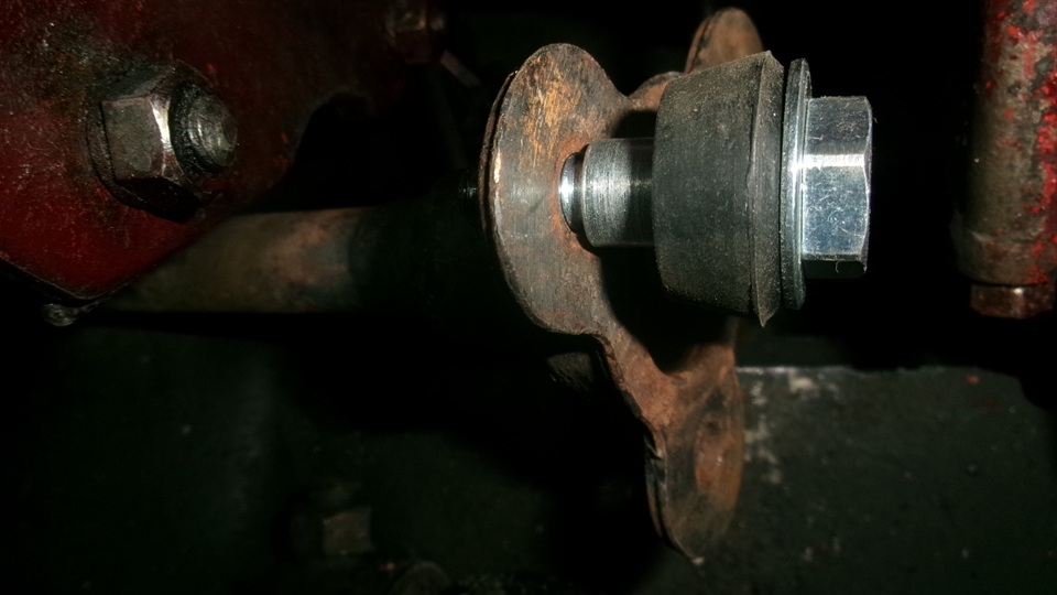
Putting this together started with a shoulder bolt with thick washer under the head, then two tapered rubber grommets, the new precision stop washer, and the locking nut. The coupling hardware kit has Whitworth standard fasteners with British Standard Fine threads, and we do not have any Whitworth wrenches. So spend some time searching for standard tools than may work with the odd hex sizes. Most inch and metric tools are too big or too small. We finally found 6-sided inch size sockets a bit oversize but fit well enough to hold the required torque. But no space for the ratchet wrench on the nut below the lower coupling flange, so that had to be a 9/16" end wrench. Unfortunately the inch size end wrench slipped on the nut when it got to high torque, and we had to switch to an 8-inch adjustable wrench (and some resulting skinned knuckles in the confined spaces).
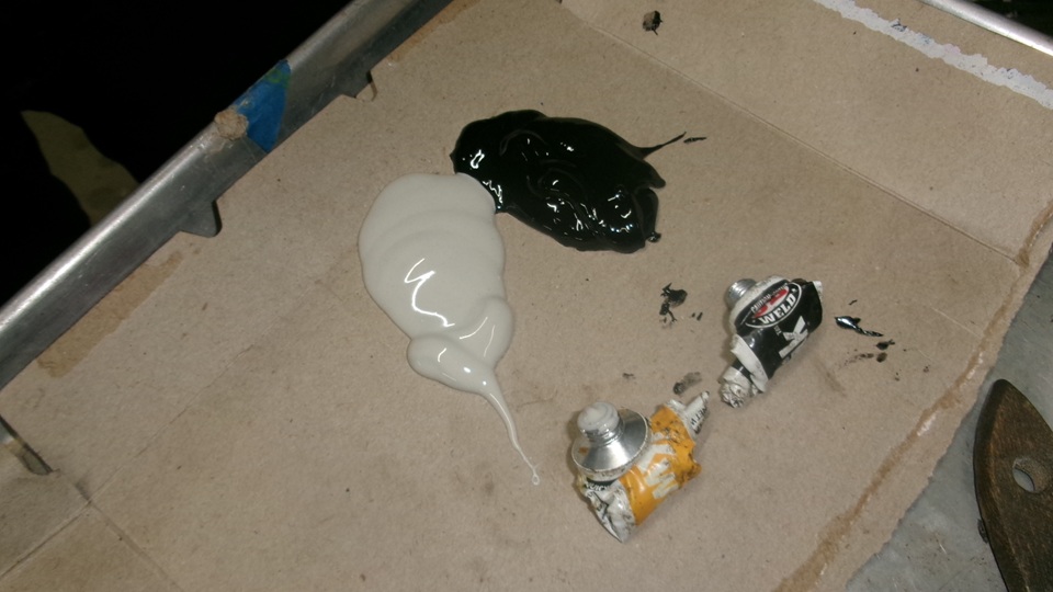
Now a huge challenge. We intend to assemble the coupling with some JB KwikWeld to fill any gaps around the thread stripped holes in the lower coupling flange to assure the new shoulder bolts will be securely locked in place and one with the flange (as the factory intended). However, the upper flange has to be fully assembled with all this hardware (except the hex nuts) before it is pushed down into engagement with the lower flange to have the nuts installed last. And whatever JB KwikWeld will be used, that has to be all in place before the final mating. And there will be limited time to work with all these parts before the epoxy will set up too stiff to work with. What could go wrong? Six minute pot life for the JB KwikWeld that's what. Navigator thought it couldn't be done. I said we don't have any other choice so set the beer down and get your hands ready, and several minutes chat and planning about the upcoming sequence of events.
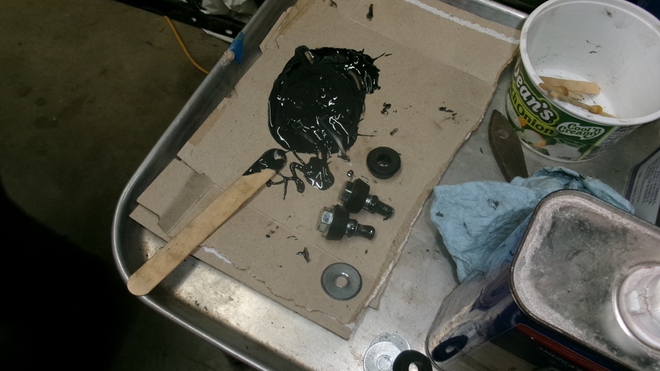
We squeezed out two small tubes of JB KwikWeld and Hardener, and start the clock when I start mixing. One minute to mix a large glob of goop, dip a stick, and start slathering the goop with fingers where it had to go, quickly. Starting with a shoulder bolt with washer under the head and one rubber grommet, slather some JB KwikWeld into the thread undercut at the shoulder, poke it through the upper coupling mouse ear hole, insert other half of tapered rubber grommet from other side, fill the resulting cavity in the grommet around the shoulder bolt with more JB, add one of the thin fender washers, slather more JB in a fillet on the washer around the exposed screw threads. Repeat all this three times for the three shoulder bolts in quick succession with rubber grommets and thin washers.
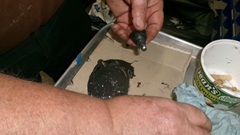
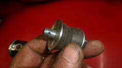
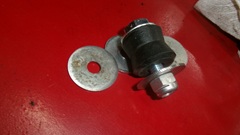
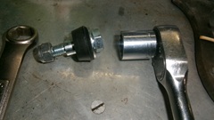
Slather more JB KwikWeld into the three stripped thread holes in lower half of the coupling before pushing the upper steering column down to engage the threaded ends of the shoulder bolts into the lower coupling. Slather more JB around thhe male threads to finish filling the space inside of the stripped threads. Then as quickly as possible, squeeze it all together like a Dagwood Special sandwich and screw the three all-steel prevailing torque locking nuts onto the threaded ends of the shoulder bolts, followed by tightening all the nuts and shoulder bolts (all in a cramped space of course). Six minutes on we were fighting the ever thickening putty while squeezing the coupling stack with huge Channellock pliers, and getting the hex nuts to start threading onto the shoulder bolts. For a while we were thinking Navi might be right (impossible to do), but persistence and lots of swearing to keep things moving finally paid off. In spite of skinned knuckles in tight quarters, the bolts were finally tight on the shoulders with rubber bushings properly compressed. Then spend a few minutes scraping away excess hardening JB KwikWeld that had oozed out of every crack and joint, and throw out the half of the hardening goop that was still on the table.
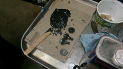
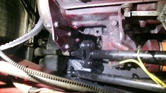
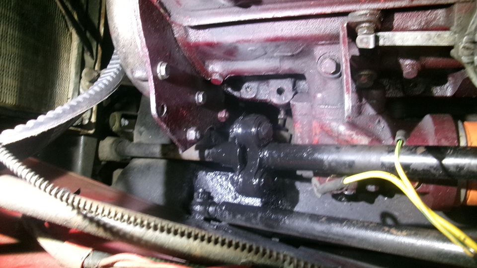
In the end, tall hex heads of the shoulder bolts stuck out far enough to graze the side of the oil pump on the engine block, and bump three times with every revolution of the steering wheel. Navi said, "You can't drive like that", and of course he was right. Just as he was talking about having to disassemble the whole works to clean off the JB KwikWeld and do it all over again, I just said, "Don't be such a pessimist, and watch my smoke". I grabbed an angle grinder with a 4-ich flap wheel, and spent about six seconds to grind one corner off the hex head of each shoulder bolt, maybe 30 seconds total, after which the steering spun freely with no interference. We Win. Still a little daylight, so roll the car out, stuff some cardboard between the steering coupling and engine, and spray some black paint on the new coupling as it was rotated, just to make it look nice. Then we had time for clean up and putting tools away, and nuke something for dinner as we can sit down to relax.
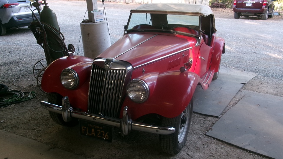
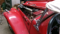
 Odd surprise, right about sun down the car's owner dropped by to have look at our handiwork, and get a full run down of everything we were doing with this car in the past few weeks. Bonnet up, doors open, walk around to scratch and sniff. She was of course very happy, but we still need to reinstall the generator and change out three brake hoses and bleed the brakes (tomorrow morning of course). And then there was "You know the screen wipers don't work very well, and there 's a little fuel drip from one of the carburetors", followed by a discussion about SAD MGs (Seasonal Affective Disorder). We need some sleep.
Thursday, July 2, 2026:
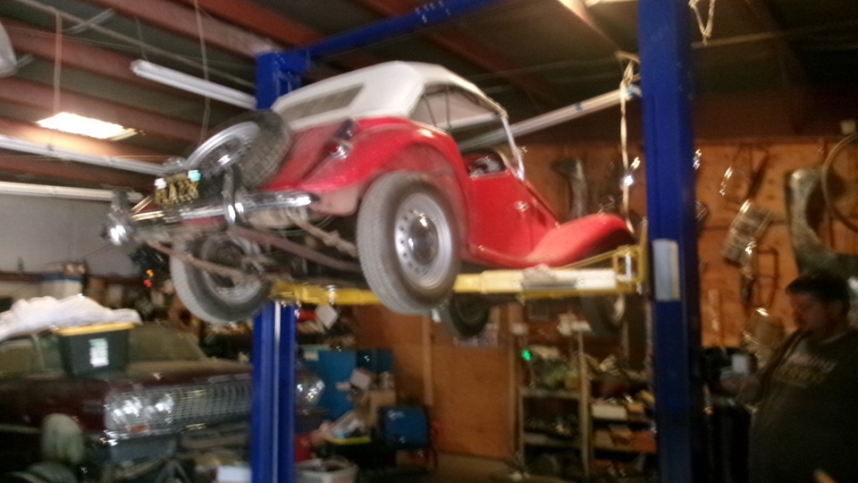
Sleep in till 8, but things to do. Bottling day at the winery, so stay out of the way there. Catching up with photos and notes from the past couple of days, and suddenly half past noon, and I need a late breakfast before getting the MG TF back inside for more work. This time we can drive it in, because the steering and brakes work. Yesterday's paint on the steering coupling is dry to the touch, no problem.
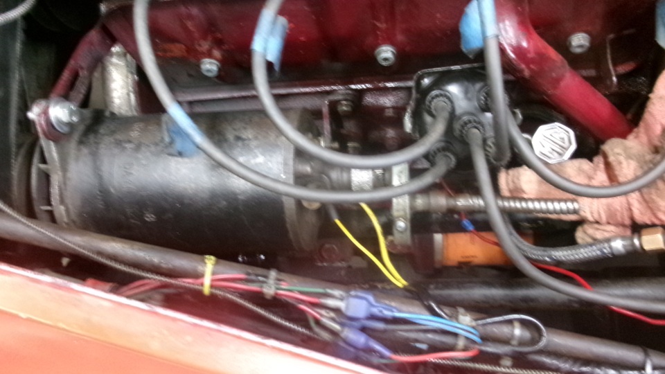
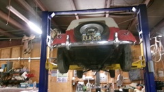
Not too long to install the generator, except the little people who designed and built this car had to be masochists. Get the wide fan belt onto the crankshaft and water pump pulleys. Set the generator in place, leaning outboard, to install two pivot bolts underneath, with bolt heads in front, lockwasher and hex nut at rear, and finger tighten those two. Pivot the generator full inboard against the engine to load the belt onto the generator pulley.then pull the generator outboard to tension the belt. Fold down the adjuster link on top in front to install the generator top bolt with flat washer to span the bracket slot, and lockwasher under the bolt head. Pull or pry generator outboard to tension the belt, and tighten the top adjuster bolt. Then the fun one, tightening the lower front bolt. Using a long ratchet handle and 1/2-inch deep well socket, reach behind the radiator, in front of the fan belt, with the deep socked nested against inside run of the fan belt, directly under the generator fan and pulley. From behind and underneath, use a shorter ratchet handle with medium length extension and 1/2-inch socket. This can be aligned close enough to tighten the lower front bolt. For the lower rear bolt, same ratchet with short extension and 1/2-inch socket, while reaching underneath with an end wrench to hold that bolt head. It helps to have done this at least once before, or remember the tools you used to take it apart. Attach two wires for Dynamo and Field control terminals, and connect the tachometer drive speed reducer to back end of the generator. Re-install distributor cap with HT wires, and ti-wrap the temperature sensor pipe to the left side radiator brace tube. Switch on, fuel pressure up, push button to start, see ignition lamp go out when evved up a bit, and back it out off the shop. Clear the space, and bring the car back in with a hard right turn to center it up and get it on the hoist for the next job.


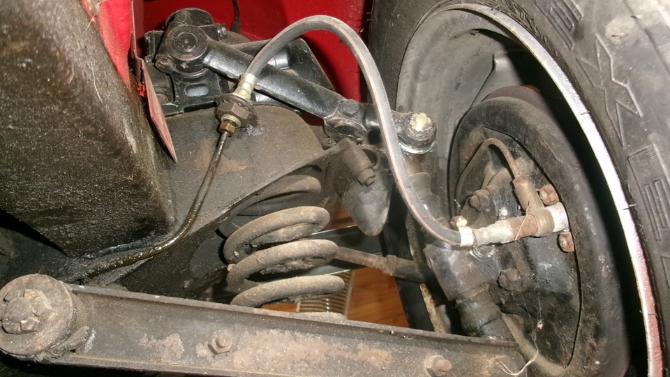
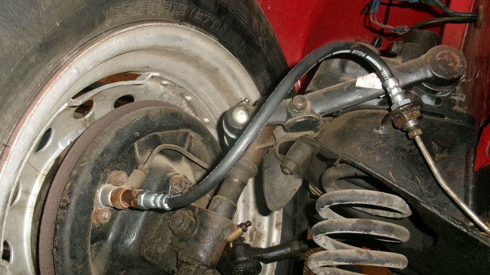
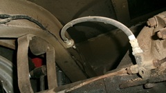
Time to change three brake hoses, starting with right front. Unscrew the inboard end pipe first, and remove large nut and lockwasher to disconnect the hose from frame bracket. Then unscrew the hose outboard end. Thus is when we discovered the hard way that there is a banjo adapter that came out with the hose, dropping two copper seal washers. For a while we thought we had received the wrong hoses, but then took the old one to tee vice to unscrew hose from the adapter, and put the adapter back in the car. Not long then to install the new hose, and get on to the other side.

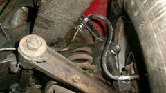
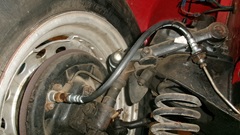
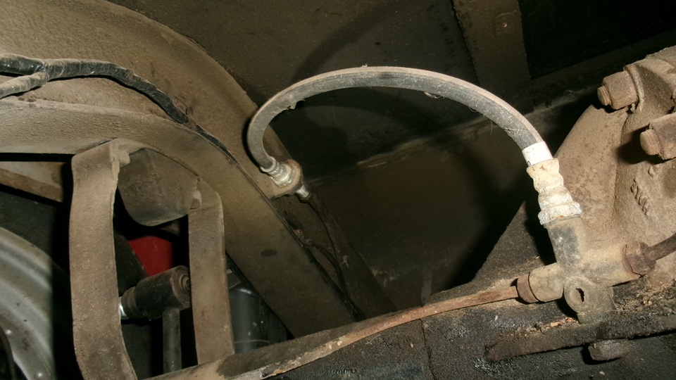
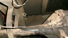
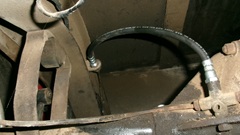
After the left front, moving on the the rear hose. Again, disconnect the pipe first, then dismount hose from frame bracket, and then unscrew the hose from the rear axle 3-way fitting. Piece of cake. Reassembly is the reverse of disassembly.
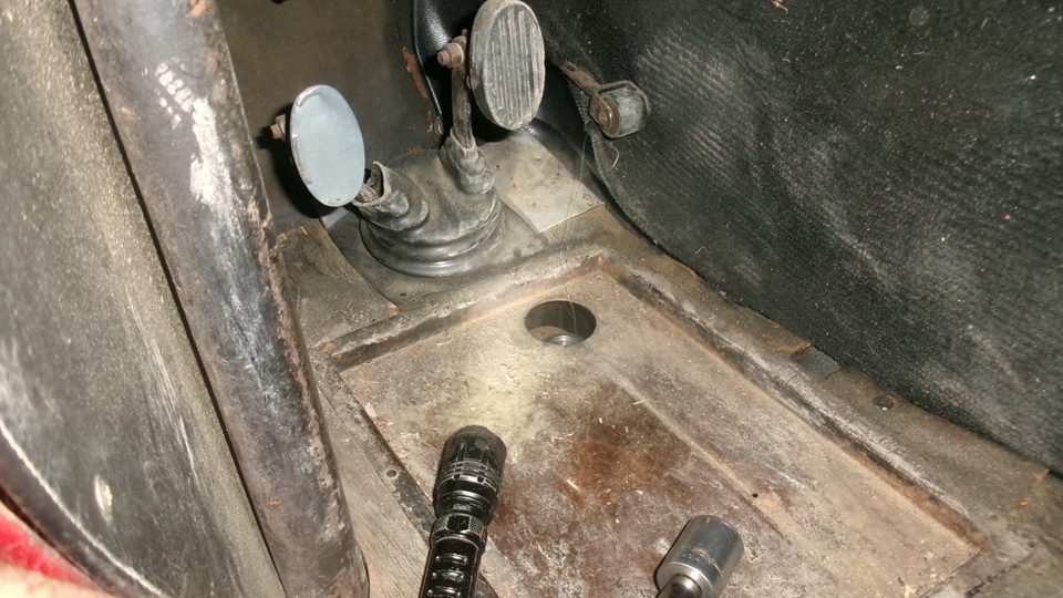
All that's left is to bleed the brakes, tight? Remove plug from top of master cylinder under the floor, check brake fluid type (yellow stuff that mixes with water is glycol based DOT3 or DOT4). Top up the reservoir, and bleed air out of the lines at four corners, beginning farthest from the master cylinder and working closer. Keep it topped up, not to run it empty, and we only had to go around once to get short pedal travel and firm brake pedal. Then there was another problem that killed another hour after dark. After a firm step on the pedal, the front brakes were dragging again, especially the right front. Bummer.

With another hour of investigation and diagnostic work, it is determined that all of the hydraulic system is good, except three of the four front wheel slave cylinders are dragging enough to prevent the springs from returning the shoes to rest. I don't recall ever seeing this issue before with front drum brakes. Usually they either work or they leak.but front slave cylinders do not normally stick when extended. Disc brake calipers can do that when their piston seals get old and stick.On a budget, try honing the slave cylinders and installing repacking kits. Otherwise put new front slave cylinders on the shopping list. Also when installing the generator, and tensioning the fan belt, we found the water pump bearings loose with the fan blade, pulley and shaft wobbling too much. Still functional for now, not leaking yet, but this is a pending future failure, so add a water pump rebuild or replacement to the parts and work list.
Late night run down the hill for sandwiches and sodas, followed by posting photos and notes for the day, and dang it was 3-am before snooze time.
Friday, July 3, 2026:
Slept in till 9. Then making an order list for the needed MG TF parts. For now the car will get out of the shop and park next door at Stu's sisters place to be out of the way. Just enough snacks for breakfast, and the larder is empty as planned. Cleaning up, putting tools away, packing all of our stuff back into the Magic Trailer to be hitting the road again. Next appointment is in southwest Oregon a few days hence. check back later.
|