Calibrating the Thermal Fuel Gauge Beginning with the 1965 model year MGB (roadster 48766 and all GT), and the 1967 model year MG Midget (52390 Mk-III with 1275 engine), the fuel gauge has a thermal actuator based on a bimetalic strip which bends when heated using electrical resistance and current. Electrical power is supplied and controlled by a voltage stabilizer for input averaging about 10 volts. The gauge modulating signal is provided by a variable resistance sender unit in the fuel tank.
If your fuel gauge is not reading properly check the input power first (with ignition on). A test light should blink on/off with about 80% duty cycle. An analog volt meter should have the needle swinging between 12 volts an 0 volts, most of the time high. A digital volt meter may be confused by this input and give faulty and eratic reading. If the power does not switch on/off in this manner, fix the voltage stabilizer before you do anything with the fuel gauge.
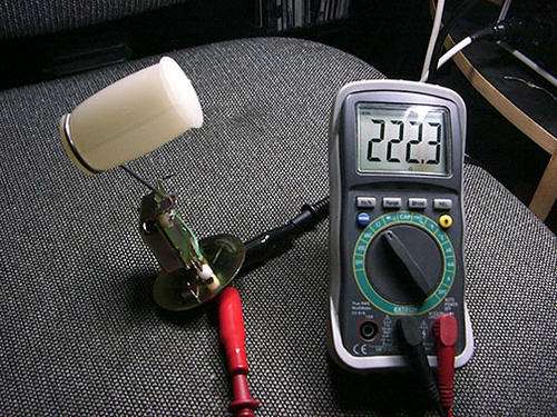
Next with ignition off use an ohm meter to check resistance between the gauge signal wire and ground. This is actually a measurement of resistance of the sender unit in the fuel tank, assuming the signal wire is properly connected. This should read low resistance with full tank and high resistance with empty tank, but it is very non-linear. If you have a good idea how much fuel is in the tank, the sender resistance should be similar to this:
| |
20 Ohms for Full
35 Ohms for 3/4
65 Ohms for 1/2
105 Ohms for 1/4
222 Ohms for empty
|
If the signal resistance is dramatically different than expected, check connection of the sender wire and operation of the sender unit before fiddling with the gauge. If input power is good, and sender resistance is in the ballpark, then you may need to calibrate the fuel gauge (or the sender unit).
This page was posted by Barney Gaylord
The balance of this article below has been supplied by
Gary Alpern, Santa Monica, CA, USA
|
Apparently with a combination of new fuel tanks and new senders there's a bigger need to calibrate both gauge and sender than there used to be. This is what you will need:
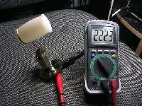
Digital Multi-meter
Resistors at the following values: 20 Ohms, 35 Ohms, 65 Ohms, 105 Ohms, 222 Ohms. Optionally you can just set the sender to these values.
A 10VDC power source. Wall warts can do this and be found anywhere from RS to K-Mart.
Needle nose or small pliers
Patience
It may be best to get power adapter that is variable from say 9VDC - 12VDC. That way you can use it for other things. Plus these things aren't calibrated exactly. 9VDC setting may very well measure 10VDC.
When you have around 1/4 tank you can safely remove the sender without spilling gas. You can try to calibrate the sender first which is much easier than getting the gauge out. It might just be enough. Or you can pull the gauge and make sure its done the first time.
From here I'll go step by step with photos. First you can go to here if you want to build a box:
www.mgaguru.com/mgtech/electric/fg_06.htm
For the people who just want to do it once go here:
www.mgaguru.com/mgtech/electric/fg_10.htm
[Note: The Jaeger electro-magnetic type fuel gauge for the MGA is similar to the early Smiths fuel gauge used in the early production MGB.]
Barney helped me a great deal. I'm just doing what he shows with different resistors. You can see everything clearly. What I'm posting shows you mainly how to do the sender, and Barney's site shows you how to do the gauge.
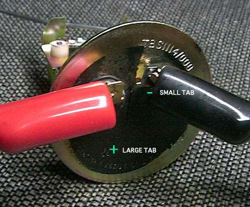
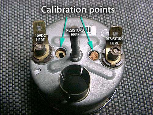
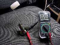
When you pull your sender (and air it out so you don't have a ton of gas smell) you will attach the probes of your DMM at the points shown here.
(Click for larger pictures)

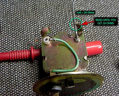
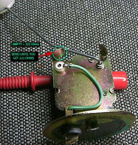
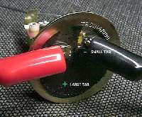
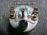
Here you will see the full tab stop and the empty tab stop. You need to swing the arm in each direction to its respective stop and bend each tab until you get 20 Ohms on the full side and 222 on the empty side. The full tab is pointed while the empty tab is rectangular.
What you're doing is calibrating the varible resistor which is the sending unit to hit the right values for full and empty. If you are less than 20 Ohms on the full side you need to bend the tab flatter which will stop the arm sooner. If you are greated than 20 Ohms you bend the tab up letting the arm travel a bit more before stopping. Same for the empty.
Finally, it has been suggested you bend the arm as a fix. NEVER bend the arm. You will throw it way out of alignment and nothing you do shown here will bring it back. The angle of the bend appears to be 20 degrees if you want to check it.
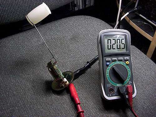
 Once you've fiddled your brains out and get close as you can, you can then use fixed resistors in the values given above. Connect one side of the resistor to the gauge tab where the sender sends its signal and the other end of the resistor grounded to the center bolt (just like you see on Barney's page).
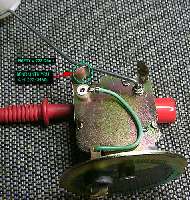
Our gauges have cruder adjustment points. As noted by another member this is a thin piece of metal so get something that fits the slot completely so you don't bend it. It is moving on a rivet. It can be difficult to to finesse the adjustment but you'll get it with trail and error. Take your time and be careful. Put your 10VDC source on the other tab and ground to the center bolt.
20 Ohms is full
35 Ohms is 3/4
65 Ohms is 1/2
105 Ohms is 1/4
222 Ohms is empty
|
|
Addendum May 29, 2015:
A suggestion from Pete Westbay:
"If you use a screwdriver to calibrate the fuel gauge (while key is on) put electrical tape on the blade, or use a plastic blade. I shorted out my voltage stabilizer until I figured this out".
|
|
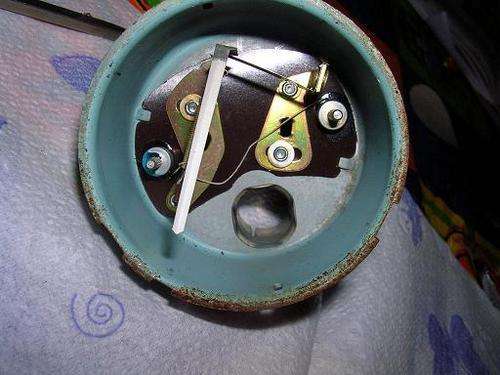
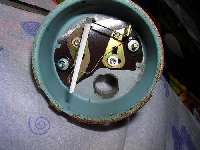 The adjusters are in relationship to the halves of the dials they inhabit. As you face the dial front the adjuster behind the half to empty does the empty section. Behind the 1/2 to full that part. You turn it like a screw although its just metal being slid through the rivet. Here's an image from Bobby Russo's post that shows the inside.
On long stretches of road its very nice to have an accurate gauge. You can save time and money if you do it right.
Additional notes:
The gauge has to be removed to adjust, as the lock bar blocks the slots otherwise.
If you only move the "Full" side plate, it will affect the position of the gauge pointer relative to "E" (when the ignition is off). If you do this in the car you may also need to run the tank down some to see what's happening near empty.
If the adjustment slides won't move, the rivet can be drilled out and replaced with a 4-40 screw, washer and nut. The screw can be loosened to make the adjustment and then tightened down to keep things from moving.
Back to MGB Tech Tips
|