 Driveshafts and U-Joints
by Tom Sotomayor
The universal joint (or U-joint - originally known as a Hooke’s joint) has been with us for quite a while. As you know, they are used to connect two or more shafts together that otherwise don’t line up, but intersect at a point. The typical configuration has two “U”s, or “yokes” connected with a “cross”, or “spider”. A driveshaft uses a U-joint assembly at either end, with an intermediate shaft in between, to connect the transmission with the rear axle.
If a car had a rigidly mounted engine, transmission and rear axle perfectly in line, the driveshaft would not need any U-joints. However, engines and transmissions are rubber mounted to keep annoying vibrations from being transmitted to the vehicle occupants. Since the rear axle is normally part of the suspension, it has to move to deal with varying loads and road conditions. All of this movement means the driveshaft needs to work with components that are constantly changing position.
The problem is a single U-joint has a “dirty little secret”. As you increase the angle between the shafts, the angular velocity of the two halves is not constant.
So, what does this mean? If an input shaft runs at a constant speed, an output shaft connected to it through a single U-joint will run at the same constant speed only if the output shaft is directly in line with the input shaft. As the chart below indicates, as the angle between the two shafts change, the output shaft will speed up for one quarter of a full revolution, and then slow down the following quarter revolution. In other words, it will speed up and then slow down twice for every full revolution of the driveshaft.
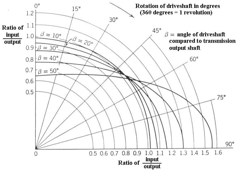
Graph for rotation error of driveshaft.
Click for larger image
There would be a real problem with component longevity if only one U-joint was used. The speed variations would be felt as vibration. The U-joints, bearings, clutch, gears, etc. would be getting constant, reversing impact loads. As the angle of the driveshaft increases, so do the speed variation and the impact load.
To solve this dilemma, two U-joints are put into the driveshaft in series, one at either end of the shaft. As one U-joint increases speed, the other decreases speed. The net effect is constant speed in, constant speed out.
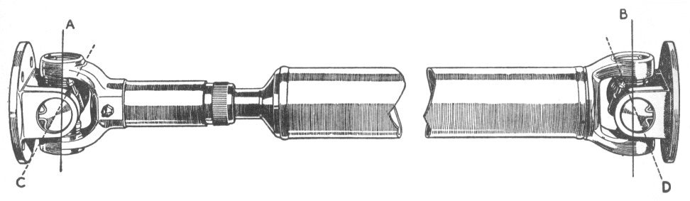
Looking at the diagram above, “C” is connected to the transmission and “D” is connected to the rear axle.
 The main purpose of the U-joints is to allow the rear axle to move up and down while still getting power. This doesn’t come for free though. As the axle moves vertically (up) and the driveshaft angle lessens, the driveshaft needs to get shorter. The vast majority of British cars including MG, Austin Healey and Triumph use a sliding splined joint between the U-joints on the shaft itself. One of the exceptions is the Sprite / Midget. It uses a sliding spline on the end of the driveshaft where it slides into the gearbox.
To work properly the U-joints must be in proper “phase” with one another. Unfortunately, Murphy’s Law rears its ugly head. Occasionally some enterprising person will disconnect the driveshaft at the splined joint to save unbolting the four driveshaft flange bolts during a clutch job. When it gets reassembled no attention is paid to the “phasing”. If they are not in phase the speed change effect will be cumulative, making the situation much worse. It can get twice as bad as a one U-joint system!
To make matters more confusing, many repair manuals show the phasing incorrectly. Referring to the sketch above, the “fixed” yokes (A and B) must always be parallel. Roughly ľ of the cars I’ve worked on with driveshaft segments, have them out of phase. Check your own car out, you’ll be glad you did!