The MGA With An Attitude
BALLASTED IGNITION SYTEM - IG-215


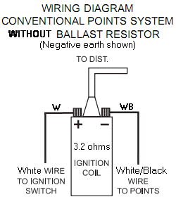
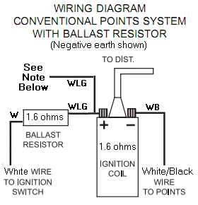
In case you might have a notion to do this with your MGA, this is the generic schematic needed to hook up a ballasted ignition system. The original non-ballasted ignition coil has primary winding resistance of about 3.2 ohms and will draw about 4 amps at full system voltage (with distributor points closed). The ballasted ignition system uses a coil with half the primary resistance, 1.6 ohms, and a series connected ballast resistor with similar resistance, giving the same total resistance and same current draw. Electrical connections are shown above.
Connect the ballast resistor between ignition switch and coil. Additional wire is optional from a relay or independent contact on the ignition switch to give full system voltage to the coil when starting. Do not connect this wire to the starter motor power cable.
Since the ignition coil does no mechanical work while at rest, all of the power flowing through it will be converted to heat.
Current I=E/R, so 12.6 volts / 3.2 ohm = 3.94 amps.
Power P=EI, so 12.6 volts x 3.94 amps = 49.6 watts.
This is similar to heat given off by a 50 watt incandescent light bulb.
Connecting two devices in series, each with half as much resistance, gives the same total resistance, same current, and same heat dissipation. Difference then is that half of the heat occurs in the ballast resistor and half in the ignition coil, each giving off 25 watts of heat, so the ignition coil does not get so hot. That's one of the advantages, when a cooler running coil may have a longer life, especially if you leave the key on with engine not running.
This will also result in half of the voltage drop across the ballast resistor, and half across the coil, so each device will see about 6.3 volts (with engine not running). In effect the coil for 12 volt ballasted ignition is really the same as a 6-volt system non-ballasted coil. None of them has any resistor inside other than the resistance of the primary coil winding. This is a ballasted ignition system, not a ballasted coil.
Now about that extra wire where the diagram says "See Note". This is optional for your conversion. Most OEM ballasted ignition systems will have this wire connected to an ignition relay or to a separate isolated contact in the starter switch or to a terminal on the solenoid on the pre-engaged type starter motor. The idea is when you pull or press or turn to start the engine, the circuit will bypass the resistor and apply full system voltage to the ignition coil. This gives the potential for a momentarily hotter spark when battery voltage drops a little while cranking on the starter motor. Without this extra bypass wire the ballasted ignition works much the same as the original non-ballasted setup with a slight drop in voltage while cranking, and the engine will start end run either way. The advantage for the bypass circuit is when the engine might be very hard to crank in cold weather or with low battery voltage, doubling the voltage on the coil may avoid a low voltage no-spark condition.
Considering that my MGA has survived more than 50 years and close to 380,000 miles without ballasted ignition, I'd be inclined to say it probably isn't necessary or much of an advantage to install. If you were to park the car outdoors in winter and expect it to start regularly in sub-zero temperatures, then it may be of some interest. Is that what you had in mind?
|