The MGA With An Attitude
Cam Lift and VALVE HEAD CLEARANCE -- CM-201
This article is in reference to using a "16" or "18" type cylinder head on a 1500 or 1600 engine. The "15" head originally used on 1500/1600 engines has 38cc volume in the combustion chamber. The "16" head used on the 1622 engine and (most) "18" heads from 1800 engines have 43cc chamber volume. Using the large chamber head on the 1500/1600 engine requires shaving the head to reduce chamber volume to retain original compression ratio. This move can result in valve head interference with top of the engine block.
On October 22, 2010, Liam O'Flaherty of Novato, California, USA, wrote:
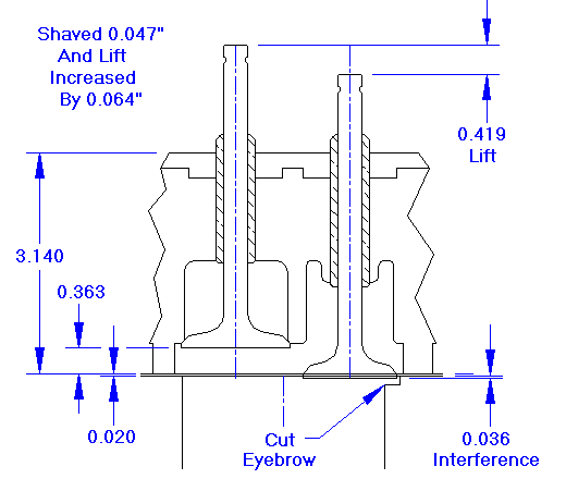
"I will be going from 43cc to 38cc and shaving .047 off the head to get it to 3.140 (from 3.187) to get to the stock compression. On checking valve lift for the .060 intake and .080 exhaust clearance, how do I go about checking this dimension with the valves at full lift? I am running a stock cam. (not a high lift cam).
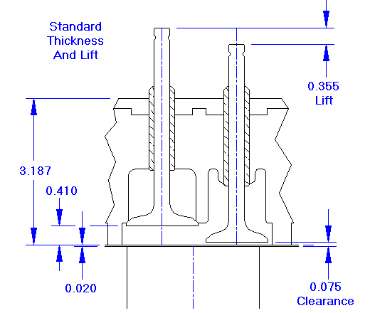
Start by measuring height of the valve head at rest relative to the gasket surface. For a stock head with full original thickness of 3.187" this may be something like .410", but it depends on how high the valve head sits after a valve job, especially if new valve seats and new valves are installed.

If the head has been milled .047" the distance from valve head to gasket surface may be more like .363". Add to this the thickness of the head gasket, which is about .020", and you get the at-rest space from valve head to top of engine block, which would be .383".
The stock camshaft has lift at the cam lobe of .250". The stock rocker arm has a mechanical ratio of 1.42:1. This gives the valve a lift of .355, full motion, if it starts with zero valve lash. For the purpose of this exercise, always assume zero rocker arm clearance, as it is possible to get this condition with an assembled engine (even though it shouldn't be that way).
Finally subtract the valve motion (.355") from the space available (.383"), and you get a meager .028" clearance at full lift. This not enough clearance for safe running at high speed. In this case you would need to grind eyebrows in top of block to increase running clearance for the valves.
For the observant working the math, you may notice if the head was not shaved this example would have .075" clearance at full lift and zero valve lash, or .090" with the normal .015" lash (rocker to stem clearance at rest). Bottom line is, these engines have close to minimal running clearance for the valve heads in stock configuration, so any reduction of clearance due to shaving the head or increasing valve lift may quickly run into a valve interference problem.

I cover this method of dimensional measurement and calculation first, and you should do this first, before you put the head on the engine and turn the crankshaft. If perchance you do have valve head interference at full lift, that would result in valve to block collision and a bent valve. When you are satisfied that you will have some clearance between the valve an block at full lift, then you can follow up with in-assembly measurement to verify the actual results. There are a couple of ways to do this.
One simple way to check actual valve head clearance in assembly is to place a dab of modeling clay (at least .100" thick) on top of the block where the valve head will approach. Then install the head gasket and the head (lightly torqued) with pushrods and rocker gear in place, and adjust valve clearance to nominal specified running clearance. Rotate the crankshaft two full turns (one turn of the camshaft) to move the valve through one cycle of full lift. Then remove the head and measure height of the impression in the clay.
The other method is a bit more "sophisticated", so to speak. This involves using soft valve springs and a long travel dial indicator to measure actual over travel motion between full lift and valve to block contact. This process is topic of the following article.
|

